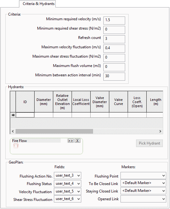
Flushing Scheduler - Criteria & Hydrants page
This page is divided into three sections:
- Criteria: specifies the criteria to be used to evaluate the effectiveness of flushing actions
- Hydrants: defines the hydrant characteristics of flushing points
- GeoPlan: sets the controls for display of flushing schedule actions in the GeoPlan window
The page is opened by clicking the Criteria & Hydrants tab on the Flushing Scheduler.
Criteria section
This section is used to:
- specify the criteria to be used to evaluate the effectiveness of flushing actions
- apply a limit to the water used in flushing
- calculate and check action timings in the flushing schedule
| Criteria | Description | Default Value |
|---|---|---|
|
Minimum required velocity |
Minimum required velocity in pipes being flushed. |
1.5 m/s |
| Minimum required shear stress |
Minimum required shear stress in pipes being flushed. A value of 0 means no check will take place. |
0 |
|
Refresh count |
The number of times the water in a flushed pipe should be refreshed. |
3 |
|
Maximum velocity fluctuation |
Maximum fluctuation in velocity in pipes that have not yet been flushed and are not being flushed in the current flushing action. |
0.4 m/s |
| Maximum shear stress fluctuation | Maximum fluctuation in shear stress in pipes that have not yet been flushed and are not being flushed in the current flushing action. | 0 |
|
Maximum flush volume |
Maximum volume of water to be used per flushing action. A value of 0 means no check will take place. |
0 |
|
Minimum between action interval |
Minimum time interval between the end of one flushing action and the start of the next. |
30 mins |
Hydrants section
This section is used to define flushing point characteristics.
Each row in the hydrants grid defines a hydrant type which can then be assigned to a flushing point in the Selected Action section of the Schedule page.
| Item | Parameter | Description | ||||||||||||||||||||
|---|---|---|---|---|---|---|---|---|---|---|---|---|---|---|---|---|---|---|---|---|---|---|
| Grid columns |
|
|||||||||||||||||||||
| Fire Flow |
For defining a hydrant type based on fire flow data. A Fire Flow Data object dragged here will be used to populate the hydrant characteristics. Note: The Hydrants grid contains additional optional attributes (for length, friction type, and roughness) that are not defined for fire flow data objects. |
|||||||||||||||||||||
| Pick Hydrant |
For defining a hydrant type based on a hydrant object on the GeoPlan. Clicking the button then selecting a hydrant on the GeoPlan will populate the hydrant characteristics from the hydrant node data. Note: The Hydrants grid contains additional optional attributes (for length, friction type, and roughness) that are not defined for hydrant nodes. |
|||||||||||||||||||||
GeoPlan section
Settings in this section affect the display of flushing schedule actions in the GeoPlan window. The display controls apply when a single Action is selected on the Schedule page.
GeoPlan themes and labelling can be used to display flushing status and velocity fluctuation graphically.
| Field | Description | Default Value |
|---|---|---|
|
Flushing Action No. Field |
The selected User Text field will be used to display the action number for pipe objects. |
- |
|
Flushing Status Field |
The selected User Text field will be used to display the flushing status value for pipe objects. Flushing status value may be set to:
|
user_text_4 |
|
Velocity Fluctuation Field |
The selected User Text field will be used to display the velocity fluctuation value for pipe objects. The field will be blank if the velocity fluctuation criterion is not exceeded before the pipe is flushed. If there is a velocity fluctuation problem in the pipe, the amount of the velocity fluctuation, the action number at which it first occurred, and the action number at which the pipe was flushed will be displayed. |
user_text_5 |
|
Flushing Point marker |
The symbol defined for the selected spatial data type will be used to mark nodes defined as flushing points in the currently selected action. |
- |
|
To Be Closed Link marker |
The symbol defined for the selected spatial data type will be used to mark links defined as to be closed in the currently selected action. |
<Default Marker> |
|
Staying Closed Link marker |
The symbol defined for the selected spatial data type will be used to mark links closed in a previous action that will remain closed during the currently selected action. |
- |
|
Opened Link Marker |
The symbol defined for the selected spatial data type will be used to mark links defined as open in the currently selected action. |
- |

