About fire flow data objects
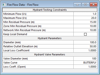
The Fire Flow Data object is used when carrying
out a hydrant testing fire flow simulation.
Fire flow data parameters are specified in the
Fire Flow Data editor. These parameters
will be used for regular nodes tested during the hydrant testing simulation.
To open the Fire Flow Data Editor, drag a Fire Flow Data object from the tree view onto the main window, or right-click the Fire Flow Data object and select .
 Show image
Hydrant nodes tested during a hydrant testing simulation will either
use parameters specified at the individual hydrant node or parameters
specified on the Fire Flow Data editor.
For more information on using fire flow data, see Hydrant
Testing.
| Section |
Description |
|
Hydrant Testing Constraints
|
|
Minimum Flow
|
The minimum flow required at the hydrant to satisfy fire fighting requirements.
|
|
Maximum Flow
|
The maximum flow required at the hydrant to satisfy fire fighting requirements.
|
|
Min Residual Pressure
|
The minimum allowed residual pressure at the test node during a fire
incident.
|
|
Zone Min Residual Pressure
|
The minimum required pressure at each node in the same fire zone as
the test node.
The fire zone can be specified on the Node
Definition page or on the Nodes
grid for all nodes.
|
|
Network Min Residual Pressure
|
The minimum required pressure at each node in the network that is not
in the same fire zone as the test node.
This constraint is used to check that required level of service is met
throughout the network at the time of the fire incident, therefore only
basic nodes with demand will be tested against the network pressure constraint.
Basic nodes without demand, and fixed head,
well and reservoir
nodes, will not be included when testing for network minimum residual pressure.
The fire zone can be specified on the Node
Definition page or on the Nodes
grid for all nodes.
|
| Keep Local Demand (check box) |
If checked, local demand (demand specified on the Node
Demand page) will be applied at the test node at hydrant testing time. If this box
is not checked, local demand will be cancelled at hydrant testing time.
Note: The setting of the Cancel Non-Hydrant
Flow at Test Nodes check box in the Fire
Flow Options dialog will override the setting of this check box.
|
|
| Hydrant Parameters |
|
Diameter
|
The internal diameter of the hydrant fitting.
|
|
Relative Outlet Elevation
|
Elevation of the hydrant outlet to be used in flow calculation RELATIVE
to the node elevation.
|
|
Local Loss Coefficient
|
Branch minor loss coefficient. The headloss coefficient due to change
of flow direction and diameter change.
|
|
| Hydrant Valve Parameters |
| Valve Diameter |
Diameter of the hydrant valve when fully open.
|
|
Valve Curve
|
The name of the hydrant valve curve.
If there is a network open, a valve curve from the current network
can be selected from a dropdown list.
|
|
Loss Coeff.(Open)
|
Local headloss coefficient when the hydrant valve is open.
|
|

