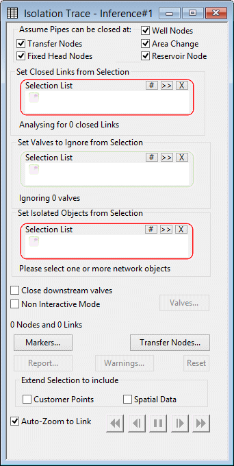
Isolation Trace dialog
This dialog is used to control the isolation trace process. The isolation trace is used to determine the nearest valves to be closed in order to isolate one or more selected pipes. The trace works outwards from selected links until the tracing tool reaches pre-defined boundary points.
The dialog is displayed (when a network is open) by choosing Tools | Isolation trace .
| Item | Description | |||||||||||||||
|---|---|---|---|---|---|---|---|---|---|---|---|---|---|---|---|---|
| Assume pipes can be closed at |
|
|||||||||||||||
| Set closed links from selection |
Optional if a selection was made on the GeoPlan before the dialog was opened. A selection of links that are to be assumed as available to be closed for isolation purposes. This selection can be used in addition to, or instead of, the boundary point options set in Assume pipes can be closed at. You may wish to use this if there are known locations where links can be closed that will not be picked up in Assume pipes can be closed at. |
|||||||||||||||
| Set valves to ignore from selection |
Optional. A selection of valves that can be ignored when deciding where links can be closed. In interactive mode, you will be asked if you want to close the corresponding link or leave it open. |
|||||||||||||||
| Set isolated objects from selection |
A selection of objects that are to be isolated on the network. The isolation trace will start from the link(s) in this selection. |
|||||||||||||||
| Close downstream valves |
If unchecked, it is assumed that valve closure can occur at links whose closure would cut off a supply of water to the area being isolated. In interactive mode, this means that you will be prompted to take an action only on links located on the upstream side of the pipe(s) being isolated. If checked, the isolation trace will prompt for valve closure for all links specified in the Assume pipes can be closed at section and whose closure would cut off the area to be isolated, regardless of whether any water is supplied via such a link. This means that you may also be prompted for downstream links. This checkbox has a similar effect on the isolation trace behaviour in the non-interactive mode. |
|||||||||||||||
| Non interactive mode |
If checked, sets the isolation trace to non-interactive mode. Makes the Valves button available. |
|||||||||||||||
| Buttons |
|
|||||||||||||||
| Extend selection to include |
|
|||||||||||||||
| Auto-zoom to link |
Applicable when running the trace in interactive mode. If checked, gives the option of the trace automatically zooming in to the link in question on the GeoPlan. If unchecked, the GeoPlan window will remain at the current position and zoom setting. |
|||||||||||||||
| Trace controls |
|


