Base Linear Structures (2D)

Base Linear Structure (2D) objects are line objects used as part of the mesh generation process carried out when undertaking 2D Modelling. The lines represent structures such as walls and weirs with a specified porosity and height which are taken into account during the 2D simulation process. Note that a Base Linear Structure collinear with the boundary of a 2D zone, will override the boundary condition of the 2D zone along the coincident portion of the boundary. The coincident portions of the wall are considered infinitely high, regardless of any crest level specified.
Base Linear Structure (2D) objects can be imported via the Open Data Import Centre or from AutoCad DWG. Lines can also be digitised directly on the GeoPlan Window.
Base Linear Structure (2D) parameters are edited in the Base Linear Structure (2D) Grid Window of the Lines Grid or the Base Linear Structure (2D) Property Sheet.
In this version, the following types of structure can be modelled: walls, weirs (thin plate weir or broad crested weir) and user controlled (flow through the structure is controlled by a user defined head-unit flow curve).
- The crest level of the structure can be defined as a constant level or as a variable crest level
- Porosity, headloss coefficient and a lateral friction coefficient can all be specified
- Flow direction can be specified as unidirectional or bidirectional
Sluices and bridges along the length of the linear structure can also be modelled by associating Sluice Linear Structure (2D) and Bridge Linear Structure (2D) objects with the base linear structure.
Breaches in the linear structure can be modelled by defining vertical movement of points along the structure via Real Time Control. See Modelling Breaches in Banks and Linear Structures for details.
Technical overview
Flow through the linear structure can be one of the following:
- free flow, which applies when the wall structure type is selected
- weir controlled flow, which applies if the weir structure type is selected
- user controlled flow, which applies if the user control structure type is selected
In the case of a weir structure type, the flow calculation is performed using the same procedures used by the 1D engine (on an element face by face basis). Currently, only two types of weir are available as line structures: thin plate weir and broad crested weir. See the Weirs topic for further information.
If the structure is a user control type, a Head Unit Flow curve is used to define the relationship between head and flow per unit length of the structure crest. The flow calculation is performed on a face by face basis with head being calculated as the difference between the upstream water level and either the downstream water level or the crest level of the structure, whichever is higher.
If the structure is a wall, the flow is calculated using the standard Roe flux calculation performed in any interior face in a 2D zone. The flow calculation is performed on a face by face basis and depends on the hydraulic variables in the adjacent elements and the crest level of the face.
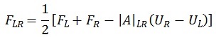
The flow is calculated using the following expression which is standard to compute a Roe flux:
|
|
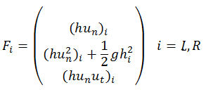
where the first two terms represent the exact flux calculation, and the last term is a numerical viscosity which vanishes if the hydraulic variables in the adjacent elements are the same. The exact fluxes are given by the following generic expression:
where: h = depth above crest level (m) un = perpendicular velocity to a face (m/s) ut = tangential velocity to a face (m/s)
The vector of conserved variables is given by the following expression:
with the first component representing mass and the second and third representing momentum. L and R denote the left and right elements to the face. |
The user is able to specify a porosity (for a wall), an energy loss associated with the presence of the structure (headloss coefficient) and a lateral friction which will depend on the tangential velocity to the structure.
Porosity
The porosity coefficient applies to wall structures.
The flow in the line structure is calculated on an element face by face basis. The porosity of the wall represents the proportion of the face that is freely open to flow. Therefore the non porous portion of the face will be considered a non porous wall with specified crest level.
The flux calculation in the case of the non porous portion of each face is computed using the following expression:
|
|
which represents the hydrostatic pressure of the non porous portion of the face in the adjacent element. |
Blockage
The blockage coefficient applies to weir structures, user control structures and also to 2D sluices.
The flow in the line structure is calculated on an element face by face basis. The blockage represents the proportion of the face through which no flow can pass. The flow through the unblocked portion of the face will be calculated using a standard weir equation based on the crest level of the face. The blocked portion of the face will be considered as an infinite wall, therefore no flow will cross it.
Lateral friction coefficient
The lateral friction coefficient is used to represent an energy loss caused by the friction of the flow against the line structure in the tangential direction. Thus, the lateral friction of the line structure will introduce a momentum term in the equations in the same direction of the line structure. This new momentum term affects the two adjacent elements to a line structure face and depends on the depth on each side of the face. The friction slope term introduced by the lateral friction in the tangential direction takes the following form:
|
|
where: Cd = adimensional friction coefficient Ut = tangential velocity (m/s) hi = depth exerting shear stress on flow (m) l = face length (m) g = gravity acceleration (m/s2) Ab = element bed area (m) h = depth (m) |
The lateral friction term can be used, for example, to represent the effect of the lateral walls in the main flow in a channel, which tend to generate a parabolic velocity profile along the cross section.
A lateral friction coefficient can also be specified for 2D sluices associated with the base linear structure.
Headloss
The headloss coefficient is an energy loss that applies to the adjacent elements of the line structure. In contrast to the lateral friction term (which only applies in the presence of tangential velocity in an element adjacent to a face belonging to the line structure) the headloss term applies to the adjacent elements in the presence of flow through the structure.
Depending on the headloss coefficient type, the headloss can be specified to be fixed (default) or per unit length. When fixed is specified, the effect of changing the mesh is minimal in the resulting headloss. When per unit length is specified, the headloss across the structure will be mesh dependent as it is calculated per unit length.
Moreover, depending on the headloss specification, the headloss coefficient can be defined as uniform, or different at the upstream and downstream elements.
The slope term introduced by the headloss in the momentum equations takes the following form depending on the headloss coefficient type:
- Fixed:
(6)
where:
Shl =slope due to headloss
d = distance between element baricenters (m)
Khl = headloss coefficient
U = velocity (m/s)
g = gravity acceleration (m/s2)
- Per unit length:
(7)
where:
Shl =slope due to headloss
Kuhl = unit headloss coefficient (1/m)
U = velocity (m/s)
g = gravity acceleration (m/s2)
A headloss coefficient can also be specified for 2D sluices associated with the base linear structure.
Collapsing walls
It is possible to set parameters for the Wall structure type which will result in the full or partial removal of the wall during a simulation depending on criteria based on the results of 2D mesh elements adjacent to the wall. The removal of the wall represents the collapse of the wall.
The criteria to trigger a collapse are defined in fields in the Definition section of the Linear Structure (2D) Property Sheet.
See the Linear Structure (2D) Data Fields topic for full details.
Remove wall during simulation
The Remove wall during simulation option can be set to either Full or Partially.
- Fully: if collapse of the wall is triggered, the entire wall object will be removed from the simulation.
- Partially: if collapse of the wall is triggered, only the portion of the wall object adjacent to the mesh elements triggering the collapse will be removed from the simulation.
Wall removal trigger
The Wall removal trigger field is used to select the variable to be used to determine whether the wall has collapsed. The trigger variable relates to the results in 2D mesh elements adjacent to the wall; for example, the Depth option uses depth of water in adjacent elements as the trigger for wall collapse.
Threshold fields
The Threshold field values to be specified will depend on the trigger variable selected in the Wall removal trigger field.
By default, if the trigger variable in a mesh element adjacent to the wall exceeds the defined threshold, the wall will collapse.
If the Use difference across wall option is selected, collapse of the wall will be triggered when the difference between the trigger variable values in the adjacent mesh elements either side of the wall exceeds the defined threshold.
Sampling elevations from a ground model
Level data for a base linear structure with Crest level set to Irregular can be updated by sampling a Ground Model. Elevations at existing vertices can be updated and new vertices inserted between existing vertices.
See Updating Network Objects from the Ground Model for details.
Results
Flow crossing the linear structure is monitored and output in the Line Results. The flow direction is determined using the same convention used for river sections, in which the first point on the line structure is assumed to be on the left hand side when facing downstream.
