Calibrating PDM Descriptors
Simulations using PDM functionality can only be run if the PDM option is enabled on your licence.
In order to calibrate a PDM descriptor, the following database items are required:
- An InfoWorks network (
 ) containing:
 - The subcatchment(s) that the PDM Descriptor, which is to be calibrated, is associated with.
- The point-type TVD connectors, which provide the references between data streams in a scalar Time Series Database (TSDB) and a subcatchment. Depending on what input data is required from the TSDB, up to three TVD connectors may be needed. See Using TVD connectors for PDM calibration for further information.
- A selection list (
 ) which contains one or more subcatchments that the PDM descriptor is associated with.
 - A scalar TSDB (
 ) that contains the required observed rainfall, and the optional potential evaporation, temperature and flow (for comparison) which may be used in the calibration operation.
 - An episode collection (
 ) which contains the flood or rainfall events which may be included in the calibration (optional).
 - A PDM calibration object (
 ) which provides the settings for the calibration operation, and performs the calibration. Information about creating and defining a PDM calibration object, and then using it to calibrate a PDM descriptor are described later in this topic.
Using TVD connectors for PDM calibration
In order for the time series data to be linked to the subcatchment/PDM Descriptor for which PDM calibration is to be performed, at least one TVD connector is required. This TVD connector must contain references to the observed rainfall and, if applicable, evaporation and temperature in the TSDB. You can also use a second TVD connector for obtaining flows from the TSDB, and a third TVD connector if, for example, potential evaporation is to be generated as a profile.
A brief overview of how each of these TVD connectors could be configured for use in PDM calibration is provided below:
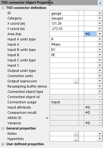
- TVD connector (1) which should contain references to observed rainfall (obligatory), evaporation (optional) and temperature (optional) in a TSDB.
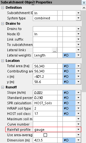
TVD connector (1) must also be referenced from the subcatchment which contains the PDM descriptor.
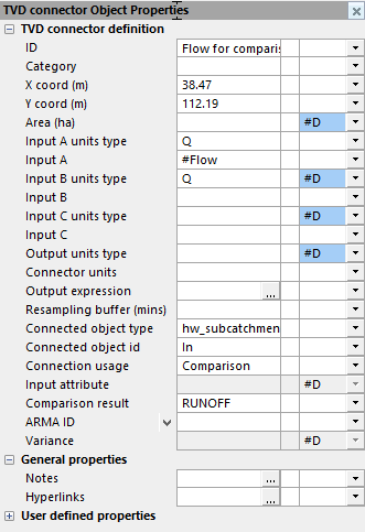
- TVD connector (2) which may be used for comparison purposes should contain a reference to the flow input from a TSDB. TVD connector (2) must also reference the subcatchment with which it is associated.
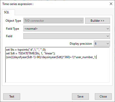
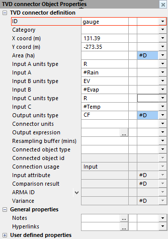
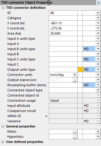
- TVD connector (3), required if, for example, potential evaporation is to be generated as a profile. This TVD connector requires an output expression to generate the profile.
TVD connector (3) must also be referenced by TVD connector (1), i.e. the one referenced by the subcatchment, to ensure that the output expression, set in TVD connector (3), is used as input to the calibration process.
Creating a PDM calibration object
To create a PDM calibration object:
- Right-click on a Model group in the tree view of the Explorer Window.
- Select the New InfoWorks | PDM Calibration option from the pop-up menu. A New Master Database Item dialog is displayed.
- Enter the name for the PDM calibration object.
- Click OK.
The new object will now be displayed under the selected model group in the tree view, and you can now use it to define the calibration parameters.
Defining the settings for PDM calibration
To define the settings for calibrating a PDM descriptor:
- Right-click on the PDM calibration object in the tree view of the Explorer Window.
- Drag and drop the network, which contains the subcatchment(s), PDM descriptor(s) and TVD connector(s), from the Explorer Window tree into the InfoWorks network drop box. The most recently committed version of the network will be used.
- Choose a Scenario from the dropdown list. This list contains all the scenarios associated with the selected network and you must choose the scenario from which the modelling parameters will be taken. If you choose to optimise any of the PDM descriptor parameters, then the updated values will be written back to the selected scenario.
- Drag and drop a selection list, which contains one or more subcatchments that the PDM descriptor is associated with, from the Explorer Window tree to the Selection list drop box. Or use the
 (Current) button to create a selection list that consists of the network objects currently selected on the GeoPlan.
 - Drag and drop a TSDB, which contains the observed rainfall, and if applicable, the potential evaporation, flow and temperature from the Explorer Window tree to the Time series database drop box.
- If you want to include an episode collection, which contains flood or rainfall events, in the calibration, then drag and drop the relevant collection from the Explorer Window tree to the Episode collection drop box.
- If you do not want to use the default method of calculating the objective function (Mean of squares of differences), then select the appropriate method from the Calculation dropdown list.
- If you want to exclude any flows below a certain volume when the objective function is calculated, then check the Exclude flows below box and then specify the required threshold in the adjacent field.
- If you want to exclude any flows above a certain volume when the objective function is calculated, then check the Exclude flows above box and then specify the required threshold in the adjacent field.
- If an Episode collection was selected in Step 6, then specify the timestep, in seconds, that will be used for simulation and calculation of the objective function in the Episode timestep field.
- If you want to specify a different timestep (24 hours is default) for the rest of the simulation, then specify this timestep (in hours) in the Non-episode timestep field.
- If an Episode collection was selected in Step 6, then check the Simulate episodes only box if the simulation should be restarted at the beginning of each episode.
- If an Episode collection was selected in Step 6, then check the Calibrate using episodes only box if the objective function is to be calculated using only the episodes. If you don't check the box, then the whole period will be used, with every timestep being given equal weight in the calculation.
- Specify the start and end date and time for the simulation in the Start and End fields. All episodes that occur during the specified period will be simulated. Any episodes that occur partially inside the period will be partially simulated. If all of the period is covered by episodes, then there will be no non-episode simulations. And, if there are no episodes during period (or none are specified at all), then the timestep specified in the Non-episode timestep field will be used throughout.
- Select the time zone for the simulation, which is used for coordinating the episode and start/end times with the timestamps of the observed data, from the Time zone dropdown list.
- Click Save to save the current settings.
The PDM Calibration dialog is displayed.
You can now use these setting to calibrate the PDM descriptor parameters.
Calibrating a PDM Descriptor
To calibrate a PDM descriptor:
- If the PDM Calibration dialog is not currently displayed, right-click on the PDM calibration object in the tree view of the Explorer Window.
- Check that the applicable settings have been defined on the Settings tab, and change if necessary.
- Click on the Calibrate tab.
- Select the subcatchment that the PDM descriptor is associated with from the Subcatchment drop-down list. This list contains all the subcatchments that are included in the Selection list specified in the Settings tab. The area and PDM descriptor from the selected subcatchment will be used in the calibration operation.
 Note
NoteSubcatchments may share the same PDM descriptor; calibrating one subcatchment will change the parameters for all subcatchments that use the same descriptor, but only the selected subcatchment’s area and TVD connectors will be used in the calibration process.
- If any of the PDM descriptor parameters are not to be adjusted as part of the calibration optimisation process, then remove the x from the Opt. column.
- If required, change any of the Values in the Parameter grid. These are the current values for the PDM descriptor, and are used as the starting point for the next optimisation cycle when you select the Optimise button. They are also used to evaluate the fit if you select the Evaluate button.
- If required, change the initial step size, which is used to adjust the parameter in the optimisation process, in the Step column. See the description of the optimisation process for information about steps and general advice on the Parameter grid settings.
- If required, change the convergence tolerance for the applicable parameters in the Tolerance column.
- If required, change the minimum and/or maximum values that a parameter can have during the optimisation process in the Minimum and Maximum column for the applicable parameters.
- If required, change the value in the Converge field. A optimisation cycle only finishes when the objective functions for all candidate parameter sets ( (i.e. all sets of changed parameters plus the original set of parameters) differ by no more than this value.
- If required, change the maximum number of iterations to be used in an optimisation cycle in the Steps field.
- Click on the Optimise button if you want to perform a cycle of optimisation, using the current parameter values as the starting point. The fit (objective function) and R2 ( coefficient of determination) will be calculated and the parameter grid and graph will be updated accordingly.
- If you would like to change any of the PDM descriptor's parameters, but you would also like to temporarily keep the PDM descriptor's current parameters, then select the Mark button. This saves the parameters to a scratch pad.
The Save Parameters Values dialog is displayed. Enter a name which will identify this set of parameters and then click on OK.
- Continue to change the parameters, and Optimise and Evaluate and Mark them as required.
If you want to recall any of the parameters previously saved to the scratch pad, select the Recall button.
The Recall Parameters Values dialog is displayed. Select the required set of parameters from the list and click on OK. The previously saved parameters will now be displayed in the Parameters grid.
 Note
NoteIf any of the values that were previously saved no longer fall within the appropriate maximum or minimum parameter values, then InfoWorks ICM displays a message and will change the appropriate maximum or minimum parameter value so that the recalled parameter are still valid.
- When you are satisfied with optimisation process, select Apply to save the current parameter values for the PDM descriptor to the scenario selected on the Settings tab.
A message is displayed asking if you want to save the current calibration parameters to the network. Click OK to save the changes.
- If you want to save the settings in the Calibrate tab, then select the Save button.
- If you want to calibrate the TVD connector for a different scenario, then select the Settings tab, choose the appliable scenario from the Scenario dropdown list, and repeat the calibration procedure from Step 3.
- Click Close to close the dialog.

You can revert any changes back to those from the version of the network selected on the Settings tab by clicking on the Reload button. However, this only reverts all changes since the last time the settings were saved using the Save button on the Settings tab.
If you prefer just to calculate the fit and R2 for the current parameter values, and update the graph, then click on the Evaluate button.
When you are finished calibrating PDM descriptors:
Any PDM descriptor parameters, which were selected to be optimised, are now adjusted and will be used when the selected scenario is run.
 button is selected in the TVD connector (3)'s Property sheet):