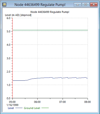
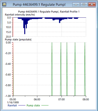
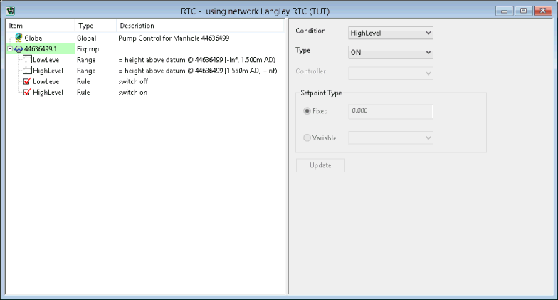
The pump at '44636499.1' is set up so that it switches on and off according to the level of water in the node at the upstream end of the pump. This stage of the tutorial adds an RTC scenario to control the pump according to the level in the manhole at '44636499', switches the pump on when the level in the manhole reaches 1.55 mAD and off when the level drops to 1.5 mAD. The scenario consists of a series of rules that define levels at which action is to be taken and the results of the action.

This stage assumes that you have started InfoWorks ICM and that the Explorer window is open, showing the RTC group icon.
- Open the 'Langley RTC (TUT)' network.
-
From the Network menu, select Scenarios | Create Scenario.
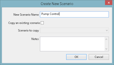
The Create New Scenario dialog is displayed.
- Name the scenario 'Pump Control'.
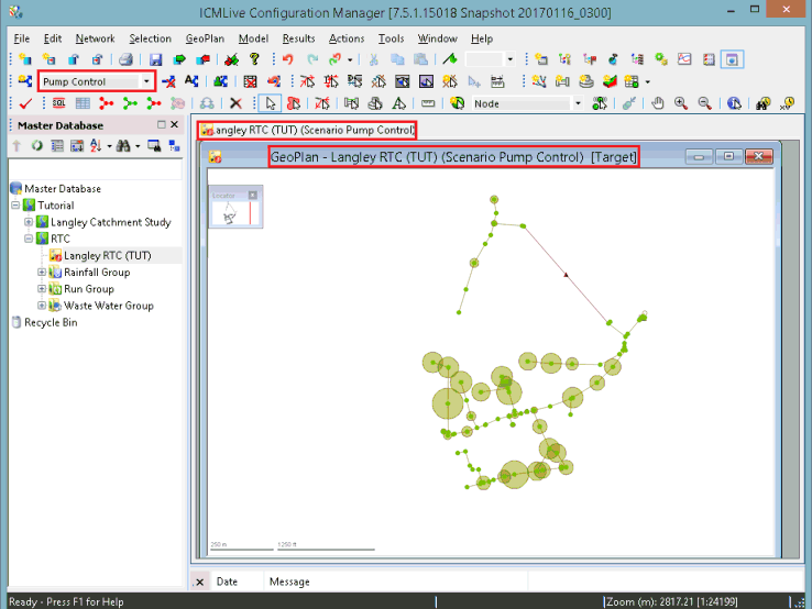
- Click OK. The dialog closes and the name of the scenario is displayed in the scenario toolbar, and on the tab and network title on the GeoPlan, indicating that this is the active scenario.
- Ensure that the 'Langley RTC (TUT)' network is still open on the GeoPlan and that the active scenario is the 'Pump Control'.
- Select RTC Editor from the Window | Grid windows option, and the RTC Editor window is displayed.
- In the Description field, enter a description, such as 'Pump Control for Manhole 44636499', for the scenario.
- Click the Update button.
The description of the new scenario is displayed in the left pane on the window
- Add the pump as a regulator in the scenario:
- Right-click the 'Global' item on the left of the dialog and select Insert regulator... from the pop-up menu.
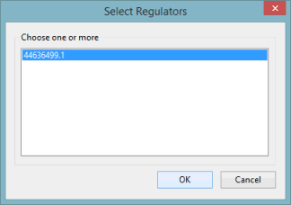
- There is only one item in the list of potential
regulators, so select it and click OK.
The pump is added to the list on the left of the dialog.
- If necessary, drag the boundaries between the column headers so that you can see the full details in the item list.
- Add ranges to specify the object that is to be associated with the regulator and the levels at which action will be taken:
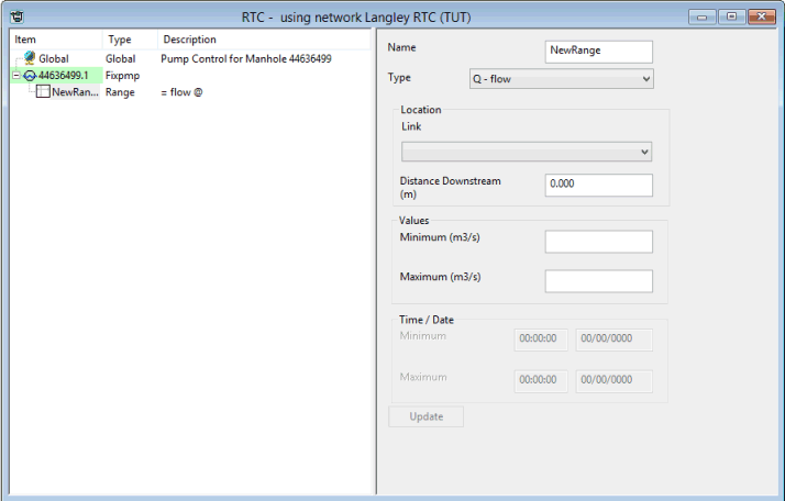
- Right-click the pump item in the list and select Insert dependent | Range. The new range is added below the pump and its details can be inserted in the right-hand pane.
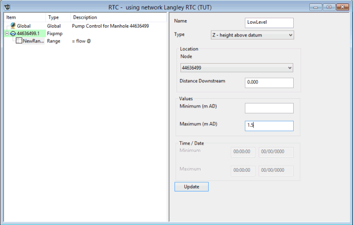
- Enter a Name of 'LowLevel' and select the Type as 'Z -
height above datum'.
Then select '44636499' from the Node drop-down list, and enter a value of '1.5' as the Maximum level.
- Click Update. The entry on the left is updated with the new details.
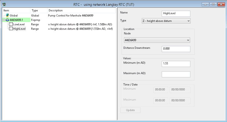
- Right-click the pump item again and add a second range. Give this a Name of 'HighLevel', select a Type of 'Z - height above datum', select the Node '44636499' and Minimum level of '1.55'.
- Click the Update button.
- Add the rules for the scenario:
- Right-click the pump item in the left pane and select Insert dependent | Rule from the pop-up menu.
- For the Condition, select 'LowLevel' from the drop-down list.
- For the Type, select 'OFF'.
- Click the Update button.
- Add a second rule with the Condition set to 'HighLevel' and the Type to 'ON', and click the Update button.
- Click the
 (Close) button to save the pump regulator definition and close the RTC Editor window.
 - Validate the network and its associated scenario.
- Commit the changes to the network.
- Click the
 (Close) button to close the GeoPlan
view.
 - Run the simulation with the RTC Scenario:
- In the Explorer window, locate the 'Run Group' in the RTC Model Group.
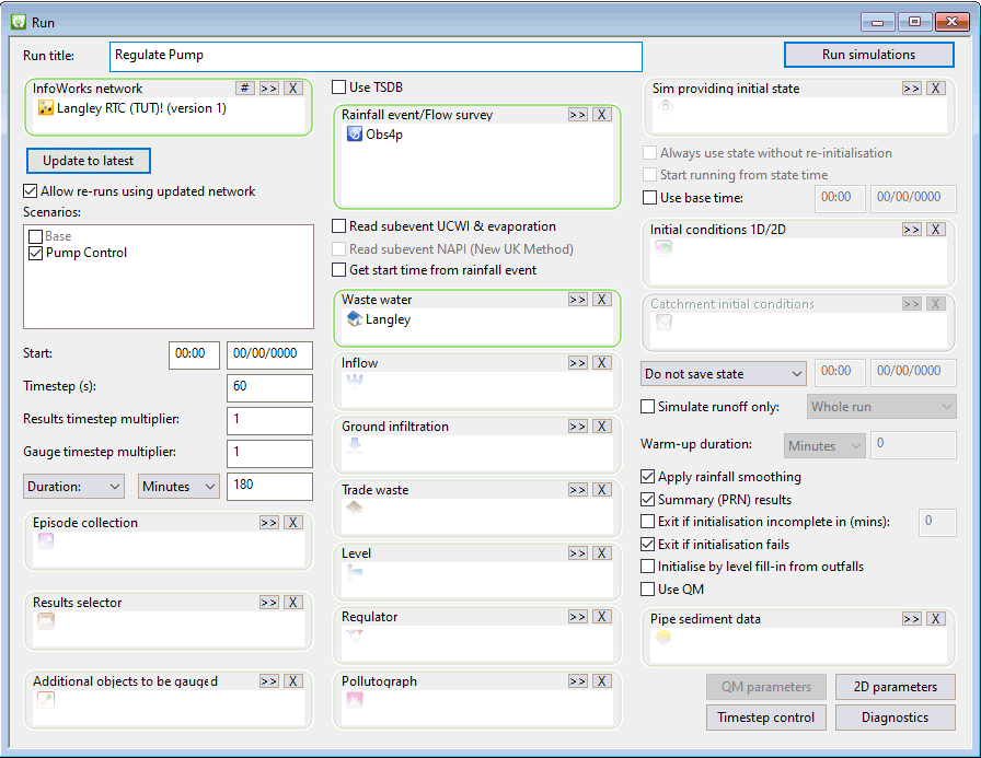
- Right-click the 'Regulate Pump' run and select Open from the pop-up menu.
The Schedule Hydraulic Run dialog is displayed.
- Click the Update to Latest button.
- Check the Allow re-runs using updated network box.
- Check the box next to the Pump Control option in the Scenarios field.
The settings for all other options remain unchanged.
- Click the Run simulations button.
A Schedule Job(s) dialog is displayed.
- Click the OK button.
InfoWorks ICM processes the run and its progress can be viewed in the Job Control window.
- View the simulation results:
- Open the simulation from the 'Regulate Pump!'
run.
The results are opened in the GeoPlan.
- Zoom in on the pump region.
- Use the
 (Graph pick) button to display
graphs of Level for '44636499' and Pump State for '44636499.1'.
 - Arrange the graph views horizonally.
- Close the GeoPlan and graph views.
A Select Regulators dialog appears.
The next stage in this tutorial modifies the RTC scenario to simulate a breakdown in the pump.



 (Expand) button to the left of the
'Fixpmp'' regulator to see the new range.
 (
(