The Network validation option can be used to show that there are no errors in the data that would affect the running of a simulation. However, this does not necessarily mean that the data is reasonable.
The Engineering validation option allows you to validate the network against a large number of other criteria. In addition, you can vary the values used in the validation rules and decide which of the validation checks are to be applied.
Following engineering validation, an information message is displayed in the Output window for each item of data that is outside normal values. You can use this window to investigate the fields for which messages have been included.
The engineering validation rules are stored in an engineering validation object.

This stage assumes that you have started InfoWorks ICM and that the Master database, containing the ICM Basic Tutorial, is opened in the Explorer window, showing the 'Langley Catchment Study' model group.
The following steps use engineering validation to fine tune the network data:
- Open the 'Langley Engineering Validation' network by either right-clicking its icon in the Explorer window and selecting Open from the context menu, or by doubling-clicking its icon, or by dragging the object to the GeoPlan.
- Right-click the 'Engineering Validation' model group and select New InfoWorks | Engineering Validation from the context menu. A New name dialog is displayed.
- Name the new object 'Default Validation' and click OK. The window closes and the new 'Default Validation' object appears in the 'Langley' model group tree.
- Right-click
the 'Default Validation' object and select Open from its pop-up, context menu.
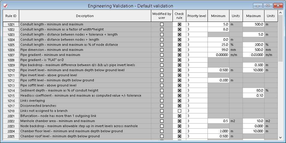
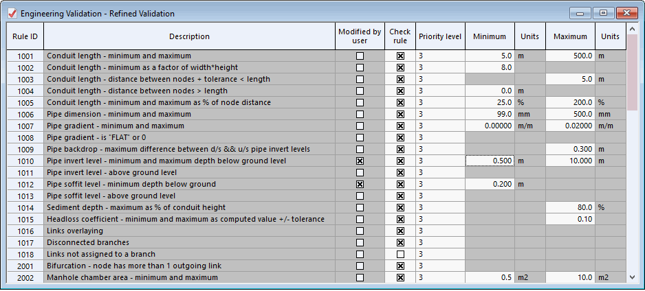
The Engineering Validation dialog is displayed, listing the validation to be tested. For example, the first rule (1001) specifies that conduits must be between 5 and 500 metres long. To start with, all the rules will be applied, using the default criteria, so close the window.
- Apply the engineering validation:
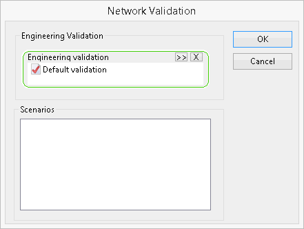
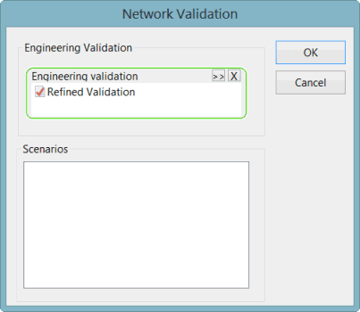
- Select Network | Validate Network and the Network Validation dialog is displayed.
- Drag the 'Default Validation' object from the Explorer window into the Engineering validation pane in the dialog.
- Click OK. The network is validated and the results are shown in the Output window.
All messages produced by engineering validation are information messages.
- You can drag the Output window into the middle of the main InfoWorks ICM window and change the column widths to make the window wider. You can click the button at the top of the Code column to sort the list in order of the message number.
- Investigate the following link messages (with codes starting I1):
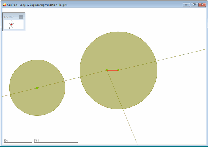
- There is one I1001 message, caused by a pipe being less than the 5 metres minimum specified in the rule. Click the message and then zoom in on the highlighted link on the GeoPlan to check that it is reasonable.
- Investigate the following node messages (with codes starting I2):
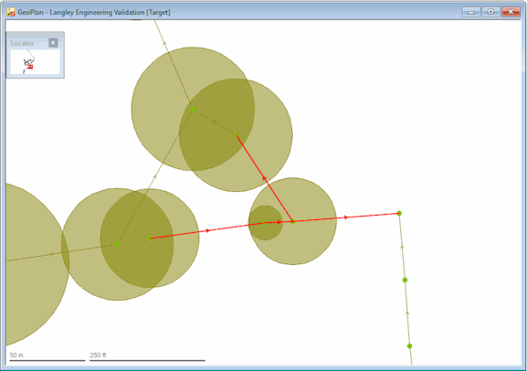
- The I2001 messages
occur when there are two or more links flowing out of a node. These messages
can indicate that direction of flow is wrong. Use the
 (Trace and select links downstream) tool
to confirm that all these cases are valid.
- The I2014 message indicates that the drop from the upstream invert to downstream invert is more than the specified value. The default value is 0, which is clearly inappropriate and needs to be changed. As a result, there are a large number of errors of this type.
- Change the engineering validation rules:
- Use the Copy and Paste options to make a copy of the 'Default Validation' object.
- Rename the new object as 'Refined Validation'.
- Open the 'Refined Validation' object.
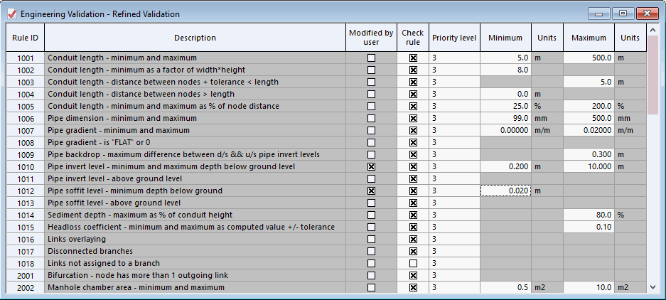
- Turn off rule 1004 by clicking the Check rule box. This means that this particular rule is now removed from the validation.
- Change the Maximum value for rule 1007 to '0.02', allowing gradients up to 1 in 20.
- Change the Minimum for rule 1010 to '0.2' and for rule 1012 to '0.02' (allowing links to be closer to ground level).
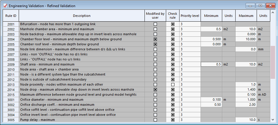
- Change the Minimum value for rule 2004 to '0.5' m and for rule 2005 to zero (allowing manholes to be at or close to ground level).
- Change the Maximum value for rule 2014 to '1.4' m.
- Turn off rule 4001.
- Close the Engineering Validation dialog.
- Click Yes when asked to save the changes.
- Validate the network again:
- Select Network | Validate Network.
- Drag the 'Refined Validation' object into the Engineering validation pane, replacing the ' Default Validation' object.
- Click OK. The number of messages has now been dramatically reduced. If required, fine tune again the validation rules.
- If any error message is still generated at this stage, please click this link to find advice on how to solve the related issue(s).
- Close the Output window.
- Close the GeoPlan view.
As you can see from the Output window, there are several messages displayed for our example network. In this tutorial, we are only to go through a few. See Validation Messages for more information about the messages displayed at Engineering Validation time.
As can be seen from this example, some problems have been identified in the network, such as problems relating to engineering validation rule 1004, which you would normally want to correct before running any simulations.


 button in the top right-hand corner of the window.
 (close) button in the upper left corner of the window.