|
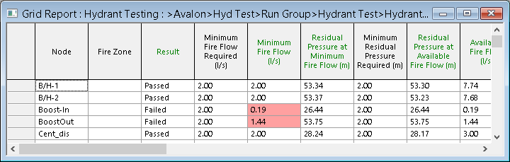
Node
|
ID of test node.
|
| Result |
Passed - The node will pass if the minimum fire flow required can be supplied
without breaching any of the pressure constraints applied.
Failed - The node will fail if the minimum fire flow required cannot be supplied
without breaching any of the pressure constraints applied.
Unknown - The test result will be unknown if the node is not tested (for example, if hydrant
flow has been set up on the Hydrant
Flow Profile page of a test node), or if the simulation
fails to converge.
|
|
Minimum Fire Flow Required
|
Minimum flow required to satisfy fire protection needs. The minimum
flow value is specified by the user in the Fire
Flow Data Item or on the Hydrant
Property Sheet of a Hydrant node.
|
|
Minimum Fire Flow
|
The smaller of the user defined Minimum Fire Flow
Required and calculated Available Fire Flow
at the test node.
|
|
Residual Pressure at Minimum Fire Flow
|
Pressure at the test node when the Minimum Fire
Flow is applied at the node.
This result is calculated only if the Calculate
Pressure at Min and Max Fire Flow option is checked on the Fire
Flow Options dialog.
|
|
Minimum Residual Pressure Required
|
The minimum allowed residual pressure at the test node during the fire
incident.
|
|
Residual Pressure at Available Fire Flow
|
The residual pressure at the test node when the Available
Fire Flow is applied at the node.
|
|
Available Fire Flow
|
Maximum fire flow that can be taken at test node without breaching pressure
constraints.
The Available Fire Flow is determined from:
- Minimum Residual Pressure
Required
- Zone Minimum Residual Pressure
Required (if Use Zone Constraints option checked)
- Network Minimum Residual
Pressure Required (If Use Network Constraints option checked)
If the pressure constraints applied cannot be met, the test node will
be Failed.
|
|
Maximum Fire Flow Required
|
A maximum flow value is specified by the user in the Fire
Flow Data Item or on the Hydrant
Property Sheet of a Hydrant node.
This information is displayed only if the Calculate
Pressure at Min and Max Fire Flow option is checked on the Fire
Flow Options dialog.
|
|
Maximum Fire Flow
|
The smaller of the user defined Maximum Fire Flow
Required and calculated Fully-open Hydrant
Flow at the test node.
This result is calculated only if the Calculate Pressure
at Minimum and Maximum Fire Flow option is checked on the Fire
Flow Options dialog.
|
|
Residual Pressure at Maximum Fire Flow
|
Pressure at the test node when the Maximum Fire
Flow is applied at the node.
This result is calculated only if the Calculate Pressure
at Min and Max Fire Flow option is checked on the Fire
Flow Options dialog.
|
|
Residual Pressure at Fully-open Hydrant
|
Pressure at the test node when the Fully-open
Hydrant Flow is applied at the node.
This result is calculated only if the Calculate Open
Hydrant Flow option is checked on the Fire
Flow Options dialog.
|
|
Fully-open Hydrant Flow
|
Flow at test node when hydrant is 100% open.
This result is calculated only if the Calculate Open
Hydrant Flow option is checked on the Fire
Flow Options dialog.
|
|
Pre-Test Pressure
|
Pressure at test node at Hydrant Testing Time
before applying fire flow. This is the result that would be obtained when
carrying out a simulation of Run Type normal.
|
|
Pre-Test Demand
|
Demand at test node at Hydrant Testing Time
before applying fire flow. This is the demand that would be applied when
carrying out a simulation of Run Type normal.
|
|
Zone Minimum Residual Pressure Required
|
The minimum allowed residual pressure during the fire incident at nodes
that are in the same Fire Zone as the test node. The test node itself
is not included.
This information is displayed only if the Use Zone
Constraints option is checked on the Fire
Flow Options dialog.
|
|
Zone Minimum Residual Pressure
|
The minimum residual pressure during the fire incident at nodes that
are in the same Fire Zone as the test node (the test node itself is not
included).
This result is calculated only if the Use Zone Constraints
option is checked on the Fire
Flow Options dialog.
|
|
Minimum Zone Node
|
Node at which Zone Minimum Residual Pressure
occurs.
|
|
Network Minimum Residual Pressure required
|
The minimum residual pressure during the fire incident at nodes that
are not in the same Fire Zone as the test node.
This information is displayed only if the Use Network
Constraints option is checked on the Fire
Flow Options dialog.
|
|
Network Minimum Residual Pressure
|
The minimum residual pressure during the fire incident at nodes that
are not in the same Fire Zone as the test node.
Note: Fixed Head, Well
and Reservoir nodes are not included in
the check for Network Minimum Residual Pressure.
This result is calculated only if the Use Network Constraints
option is checked on the Fire
Flow Options dialog.
|
|
Minimum Network Node
|
Node at which the Network Minimum Residual Pressure
occurs.
|
| Maximum Velocity Required |
The maximum allowed velocity in any of the links in the network during the fire incident.
This information is displayed only if the Use maximum velocity option is checked in the Fire
Flow Options dialog.
|
| Maximum Velocity |
The maximum velocity experienced in links in the network during the fire incident.
This result is only calculated if the Use maximum velocity option is checked in the Fire
Flow Options dialog.
|
| Maximum Velocity Link |
The link at which Maximum Velocity occurs. |