Adding a 2D Sluice Linear Structure to an InfoWorks ICM river model
 Preamble
 Before making a start on this tutorial, it is important to ensure that the units of measurements shown in InfoWorks ICM displays are set to metric. For this, select Options... from the Tools menu and click on the Units tab. Ensure that default units are set to Metric (Native).
This tutorial has been designed to help you understand the various steps involved in adding a 2D sluice linear structure to a 2D zone in InfoWorks ICM. The Adding a 2D base linear structure to a 2D zone in InfoWorks ICM river model tutorial should be completed before starting this tutorial.

Before making a start on this tutorial, please ensure you have read the Tutorials Welcome page as it contains important information about installing the provided example data.
When adding 2D sluice linear structures to a model you will need a 2D base linear structure and a 2D zone ready. It is also advantageous of having good ground model data for the surrounding area available.
- Make a copy of the Adding a 2D base linear structure - completed network created in the earlier exercise:
- Open the provided transportable database by using the File | Open | Open transportable master database... menu item.
- Browse for the transportable database, which can be located in the Example Data Directory where the tutorials files have been installed. Click on Open.
- The transportable database opens in an Explorer window.
- Expand the contents of the Model group by clicking on the
 button.
 - Right-click on the Adding a 2D base linear structure - completed network and select Copy from the popup menu.
- Back in your current master database, right-click on the Model group where you want to place the network and select Paste: Adding a 2D base linear structure - completed (with children).
- The network gets copied inside the Model group of your choice, inside the master database.
 Tip
Tip The database name is of the type IWICM_Examples.icmt.
- Rename the copy Adding a 2D sluice linear structure by right-clicking on the network object in the Explorer window and selecting Rename. In the Rename InfoWorks network dialog, type in the name of the new network and click on OK.
- Drag the Adding a 2D sluice linear structure network onto the main window.
- Drag the DTM ground model imported in an earlier exercise onto the main window.
-
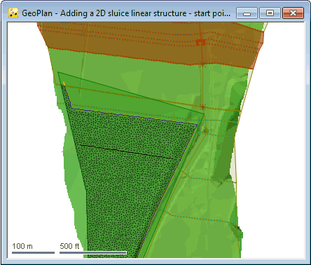
The first step is to add a 2D sluice linear structure into the 2D zone. These structures can be used to present bridge openings or sluice. The 2D sluice linear structure represents an opening of the wall that never collapses during the simulation. We are going to draw a line in the 2D zone and define it as a 2D sluice linear structure:
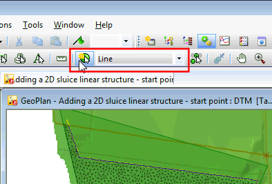
- From the New Object toolbar item, select Line as the required object type. Then select the New Object button
 .
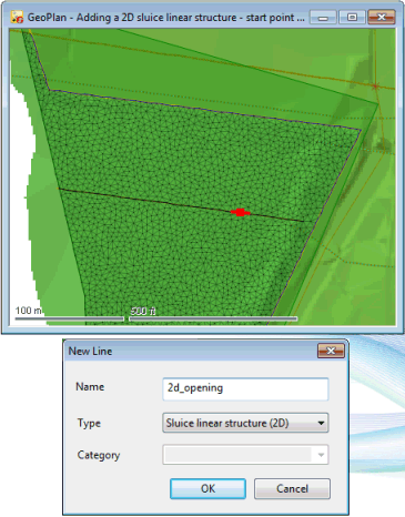
. - Draw in a new line as shown in the screenshot below. When prompted, set the name as 2d_opening. It is also very important to remember to set the line type to Sluice linear structure (2D).
- From the New Object toolbar item, select Line as the required object type. Then select the New Object button
- Next, use the Properties tool
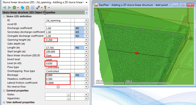
 , select the 2D sluice line and set the various parameters required. In particular, set the Base linear structure (2D) ID to Dam. This will link the 2D sluice linear structure to the existing 2D base linear structure. Also set the Start length (m) to 100. By doing so, the location of this 2D sluice linear structure will be moved 100m from the start (as drawn from left to right) of the Base Linear Structure, towards the middle of the 2D wall providing a better presentation as an opening.
 - All other parameters should be set as in the screenshot below (Opening height set to 0.2 m, Level set to 0.05 m, Blockage left at 0, Headloss coefficient set to 0.5 and Lateral friction coefficient set to 0.2).
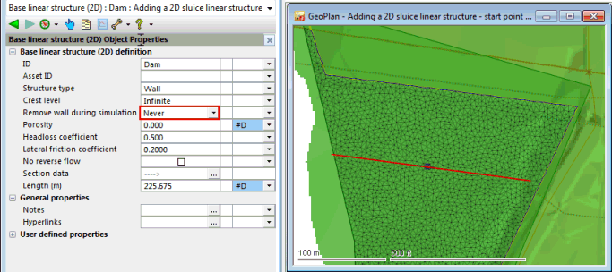
- A wall can be set up for either never collapse, partially collapse (the segment of the wall adjacent to the 2D element in which the condition has been met will collapse) or fully collapse, in which the entire wall collapses, as soon as the condition is met, at any point along the wall.
- Next, use the Properties tool, select the 2D base line and in this tutorial, we use the existing 2D base linear structure as a never collapse wall, set Remove wall during simulation to Never and ensure that Porosity is left at 0.
- Re-mesh the 2D zone, this will include the 2D opening in the 2D mesh. The new mesh job result then needs to be loaded:
- Use the Selection tool
 to select the 2D zone.
 - Create a mesh by choosing Model | Meshing | Mesh 2D zones…. If the DTM Ground Model object is not present in the Ground Model drop target of the Mesh 2D Zones dialog, drag and drop it there and press the OK button.
- On the Schedule Job(s) dialog that gets subsequently displayed, select the computer that is going to generate the mesh (This Computer by default) and press OK to initiate the mesh generation process. Wait for the process to complete. The time taken will vary depending on the PC used, but will typically be just a few seconds for this particular model.
- Once the process has finished and the 2D mesh has been generated, a popup will be displayed in the lower-right corner of the screen.
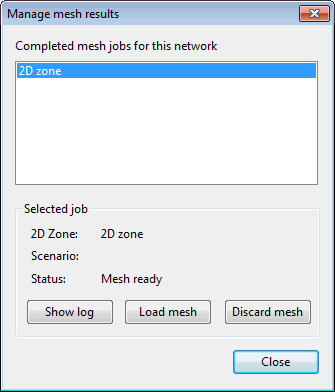
- The 2D mesh can now be loaded into the model. Select Meshing | Load mesh job results… from the Model menu. In the Manage mesh results dialog, select 2D zone from the list and click on the Load mesh button.
- Click on Close to close the dialog.
- Use the Selection tool
-
Finally, use the Validation toolbar button
 to validate the whole model to ensure the changes have not introduced any accidental errors into the model.
- Click on OK in the Network Validation dialog that gets displayed.
- There should be no errors highlighted in the Output window.
- Changes made to the network must now be committed to the Master Database so that they become available to other users.
- In the Explorer window, right-hand click on the Adding a 2D sluice linear structure network and select Commit changes (save to master).
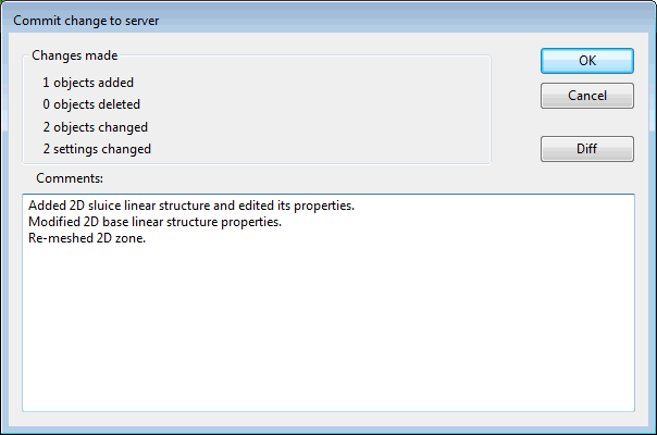
- The Commit change to server dialog is displayed.
- Type in any notes as appropriate.
- Click on OK to commit the changes and close the dialog.
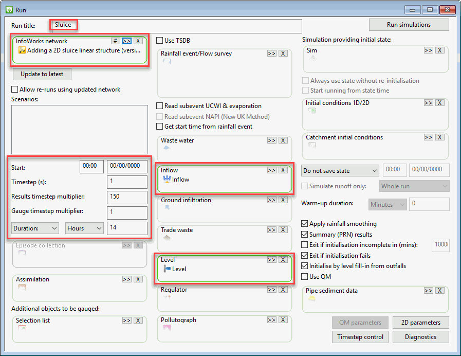
- Create a new run and define the run parameters as shown in the screenshot below:
- Create a new run by right-hand clicking the Model Group in the Explorer window.
- Select New InfoWorks | Run. The Schedule Hydraulic Run View dialog is displayed.
- In the Schedule Hydraulic Run View dialog:
- Enter a name in the Run title (Sluice)
- Drag and drop your network (Adding a 2D sluice linear structure) in the InfoWorks Network drop target.
- Drag and drop the Inflow hydrograph in the Inflow drop target (This hydrograph has been added to the model in step 5 of the Building a river model in InfoWorks ICM mini-tutorial).
- Drag and drop the Level hydrograph in the Level drop target (This hydrograph has been added to the model in step 5 of the Building a river model in InfoWorks ICM mini-tutorial).
- Set the Timestep to 1 second and the Results timestep multiplier to 150.
- Set the Simulation time to 14 hours.
It is worth noting that 1D-2D models will typically have a lower timestep than 1D-only models. In this example we will be using 1 second, but below 10 seconds is perhaps more common.
- Press the Run simulations button.
- On the Schedule Job(s) dialog that gets subsequently displayed, choose which computer will carry out the simulation (This Computer) and leave the other parameters as they are (store results locally and start the simulation now). Press OK to start.
- Once the simulation has completed (the simulation icon in the Explorer window will turn from blue to green and the Job Control window will show a green row with a status of Ended for the simulation) you can look at and analyse the results by dragging and dropping the DWF simulation from the Sluice run onto the main window.
- Drag the DTM ground model onto the main window.
- Modify the 2D zone configured in the 2D Zone tutorial so that low flows and depths have a higher visibility. Please refer to the previous tutorial for more information.
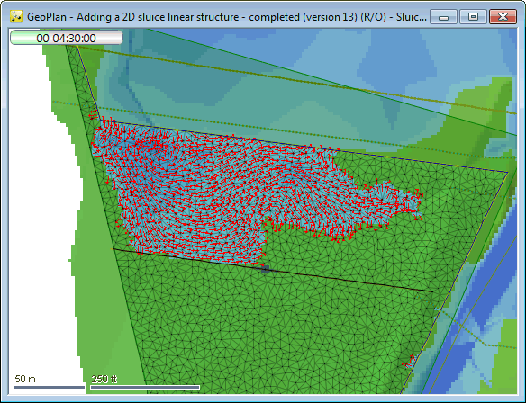
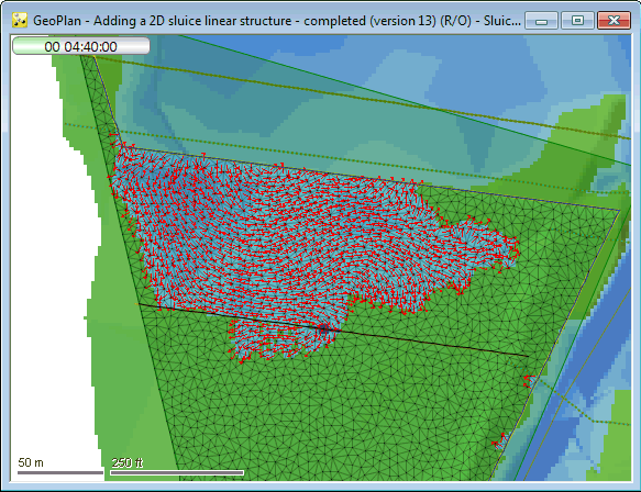
- The two following screenshots have been obtained using the modified 2D zone theme and the same flood theme as described in the 2D Zone tutorial.
The simulation has created a large number of results, which you can now inspect. The results of a simulation can be investigated in different ways and the tools available to do so are similar regardless of the network. Please refer to the Viewing Simulation Results 2D Zone topic of the Adding a 2D zone to an InfoWorks ICM river model tutorial for more information.
 Back to 2D Base Linear Structure Tutorial page.
 Back to 2D Zone Tutorial main page.
